If you’re planning to order injection molded parts, you probably already know that designing plastic parts well is not just about shape and aesthetics. One of the trickiest and most critical aspects is dimensioning injection molded parts correctly — that is, specifying the exact dimensions, tolerances, and geometric control so the parts come out of the mold and fit into your assembly without rework or scrap.
At LXG Mold Tooling, we see many design revisions arrive late because clients underestimated how complex dimensioning can be in plastic. So in this guide, I’ll walk you through what dimensioning means in injection molding, what constraints you must live with, how to specify tolerances, common pitfalls, and tips for getting it right. Think of it like a conversation with your manufacturing partner — let’s align expectations so your parts arrive ready to use.
Understanding the Basics: What Is Dimensioning in Injection Molding?
When designers and engineers “dimension” a part, they define the exact sizes (length, width, height, hole diameters, wall thicknesses, etc.), the acceptable variation (tolerances), and geometric relationships (parallelism, flatness, concentricity, etc.). In injection molding, dimensioning has two broad categories:
Linear dimensions and tolerances — e.g. this hole must be 10.00 mm ± 0.05 mm.
Geometric tolerancing / GD&T — controlling flatness, perpendicularity, true position, etc.
Because plastic shrinks, deforms, and is affected by mold cooling, dimensioning for injection molded parts is more challenging than for machined metal parts. You must design with the material and process in mind.
Why It’s Critical for Ordering Parts
If tolerances are too loose, your parts won’t fit, or assemblies may rattle or leak.
If tolerances are too tight, molding costs jump — molds must be finer, processes more controlled.
Poor dimensioning leads to successive redesigns, delays, and waste.
So when you order molded parts, having the right dimensioning ensures the parts come off the mold and plug into your products with minimal adjustments.
Key Factors That Affect Dimensioning
Here are the main variables you have to consider when dimensioning injection molded parts:
1. Material Shrinkage & Behavior
Each plastic has its own shrink rate. For example, semi-crystalline plastics (like nylon, PP) tend to shrink more and less predictably than amorphous plastics (like PC, ABS). If you ignore or underestimate shrinkage, your final dimensions will be off.
2. Wall Thickness & Uniformity
Thicker walls cool slower, causing differential shrinkage, warpage, sink marks, and dimensional inaccuracy. Good practice is to keep wall thickness consistent and avoid abrupt changes.
A rule from design guidelines: walls should not drop below 40–60% of adjacent wall thicknesses; transitions should be gradual.
3. Draft & Ejection
You must include draft (a slight taper) on vertical walls to let the part eject cleanly without dragging against the mold face. Without draft, dimensions will distort or the part might get damaged. A rough guideline is 0.5° to 2° draft, depending on depth and texture.
4. Gate Location, Flow & Fill Patterns
Where the plastic enters (gate), how it flows, and how it cools influences the final dimension. Poor flow can cause differential shrinkage, warpage, and dimensional drift. The mold design and gate position must align with your critical dimensions.
5. Mold Tool Quality & Stability
Even a well-dimensioned design fails if the mold itself is inaccurate or poorly maintained. Tool machining tolerances, wear over time, and mold stability affect how well the part holds dimensions.
6. Process Control & Consistency
Temperature, pressure, cooling rate, machine calibration — all must be controlled. Variation here causes part-to-part dimensional variability. Good molders use SPC, cavity pressure monitoring, and first-article inspection to control it.
7. Geometric Tolerancing (GD&T)
In more complex parts, GD&T helps you specify which dimensions are critical and how they must relate to each other (e.g. hole location relative to a flat surface). Using a universal language like GD&T (e.g. per ASME Y14.5) avoids ambiguit
How Much Tolerance Can You Expect?
One of the first questions a buyer asks is: “How tight can the tolerances be for injection molded parts?”
Typical tolerances for injection molding are often around ±0.1 mm (0.004 in) for many features. But for critical dimensions in small parts, you might aim for ±0.025 mm (±0.001 in) or even tighter — though achieving that requires high-end mold design, process control, and materials.
Be realistic. The tighter the tolerance, the more expensive it becomes, and the more risk you accept. In many assemblies, you can relax non-critical tolerances to reduce cost.
Also, standards like ISO 20457 and ISO 20461 guide general and linear tolerances for plastic parts.
Step-by-Step: How to Dimension an Injection Molded Part
Here’s how we at LXG Mold Tooling approach dimensioning when you come to us with a design:
Step 1: Identify Critical Dimensions
First, we review your CAD/drawings and ask: which dimensions must absolutely be correct for assembly, sealing, mechanical function, or aesthetics? These are your “critical dimensions.” Everything else is secondary.
Step 2: Apply Design-for-Manufacturability (DFM) Checks
We examine the design to ensure walls are uniform, transitions are smooth, sharp corners are avoided, ribs are well proportioned, etc. For example: rib thickness should be ~50–70% of wall thickness; rib height ~2.5–3× wall thickness.
We also check for undercuts, gating constraints, and draft requirements. (Undercuts may require side actions in the mold, which adds cost.)
Step 3: Assign Tolerances
We categorize tolerances:
Feature-level tolerances (e.g., hole diameters, slot widths)
Overall tolerances (e.g., outer dimensions)
Geometric tolerances (GD&T) for relational controls
We balance between “tight enough to work” and “loose enough to mold affordably.”
Step 4: Simulate & Tool Design
Using mold flow and simulation software, we predict warpage, shrinkage, cooling gradients, and stress. This helps refine gate location, cooling circuits, and cavity layout so the molded part comes as close as possible to nominal dimensions.
Step 5: First Article Sampling & Validation
Once the mold is built, we produce a First Article sample. We measure every critical dimension (using CMM, micrometers, 3D scanning) and compare against your spec. If discrepancies arise, we make tool corrections.
Step 6: Qualification & Production Control
Once validated, we lock in parameters, monitor process variation (SPC), and periodically recheck dimensions. Any drift is flagged early to prevent out-of-spec parts.
Common Dimensioning Pitfalls & How to Avoid Them
When clients design without this background, problems creep in. Here are some pitfalls we see often — and how to guard against them:
Mixing units or ambiguous tolerances — Always use consistent units and clear tolerance notation.
Dimensioning to the mold rather than the part — Your drawing should show final part dimensions, not mold features.
Specifying extremely tight tolerances on large features — dimensional variation scales with size; you can’t expect ±0.001 mm over a 200 mm span easily.
Neglecting shrinkage data in dimensioning — Always factor in material-specific shrink.
Geometry that fights the mold design — deep bosses, sharp corners, heavy transitions — they all distort dimensions.
No allowances for tooling corrections — expect you may need small tool tweaks after first shots, so leave margin for adjustment.
Dimensioning Best Practices: Tips & Rules of Thumb
Here are some rules we at LXG Mold Tooling always follow when dimensioning injection molded parts to deliver quality results:
| Rule | Practice |
|---|---|
| Uniform walls | Try to keep wall thickness changes gradual — avoid sudden jumps. |
| Minimum wall thickness | Depends on plastic, but many designs land in 1–5 mm range. |
| Draft angles | Apply at least 0.5° to vertical surfaces, more depending on depth/texture |
| Ribs & bosses | Rib thickness ~50–70% of wall; boss base radius ~0.25× thickness; spacing 2 to 3× thickness. |
| Smooth transitions | Use fillets and gradual thickness changes to avoid stress concentration. |
| Define datums | Choose stable surfaces as datums for measurement and inspection. |
| Use GD&T | For complex parts, control relationships (parallel, perpendicular, position) rather than just linear sizes. |
| Pilot/over-sizing tooling allowance | Plan for small tool corrections during first runs. |
| Statistical sampling | Use SPC to understand process variation and capability. |
| Expect some deviation | Don’t promise impossible tolerances — be realistic in what the process can deliver. |
How LXG Mold Tooling Helps You Dimension Right
As a customer, when you partner with LXG Mold Tooling, here’s how we ensure your dimensioning investment pays off:
Expert DFM review — Our engineering team reviews your CAD to flag dimensioning risks.
Simulation-led tooling — We use mold flow and warpage prediction to preempt dimensional errors.
Tool precision & correction — Our molds are machined to tight tolerances and fine-tuned after first shots.
Metrology support — We have CMM, 3D scanning, and inspection systems to validate your dimensions.
Process control — During production, we monitor variation and lock down parameters to preserve your dims.
Transparent communication — We work with you to trade off tolerance vs cost, and help you choose practical dimensioning that meets performance without overengineering.
Real-World Scenario: Dimensioning a Plastic Enclosure
Let’s walk through a short example to show how dimensioning plays out in a typical part — say, an electronics housing with screw bosses, mounting holes, and snap fits.
Critical Dimensions Defined
The mounting pattern (hole spacing) and boss height are the critical dimensions. They have to coordinate with the metal chassis that the part mounts onto.Wall & Boss Design
The shell wall is set at ~2 mm. Boss thickness is designed at ~1.2 mm (60% of wall) with fillets to transition smoothly. Draft of 1° is added to vertical side walls.Assign Tolerances
The mounting holes (e.g. Ø4.5 mm) get ±0.05 mm tolerance; boss height may allow ±0.1 mm. Noncritical features get wider tolerances (±0.2 mm).Simulate & Plan Gate
Mold flow simulation reveals some warpage in the far corner — so gate is placed to feed that region, cooling channels balanced, and ribs added to brace weak zones.First Article & Adjustment
After first shots, we measure the mounting pattern; it’s off by +0.07 mm in one axis. We mill a cavity side to bring it back. The next batch comes within tolerance.Production & Control
We run SPC on hole spacing and dimension drift. If trending, we stop and recalibrate.
Because of this cautious approach, the molded enclosures slot into your assembly, bolts go in without force, and end users see nothing but a clean, functional product.
Summary & How to Move Forward
Dimensioning injection molded parts is more than just “marking sizes” — it’s balancing design intent, material behavior, mold capability, and cost.
You must understand shrinkage, wall thickness, draft, tooling design, and process variation.
Be realistic with tolerances — use tighter ones only where needed, relax others.
Use GD&T when features relate to each other.
Partnering with a manufacturer that has metrology and tool correction skills (like LXG Mold Tooling) gives you the best chance of getting exactly what you need the first time.
If you’re ready to take your design from concept to mold-ready, we at LXG Mold Tooling are here to help. Send us your CAD or drawing, and we’ll work with you to define dimensioning, tolerances, and mold strategy that meets your performance and budget goals.
3 Steps For Precision Manufacturing
Share Your Files
We’ll sign an MNDA and assess manufacturability for free.
Recieve A Quote
Clear pricing and lead times, no
surprises.
Place Your Order
Lock in production and move forward with confidence.
Get A Quote Now and let’s build smarter, faster, and stronger — together.
Our Testimonials
our client say's
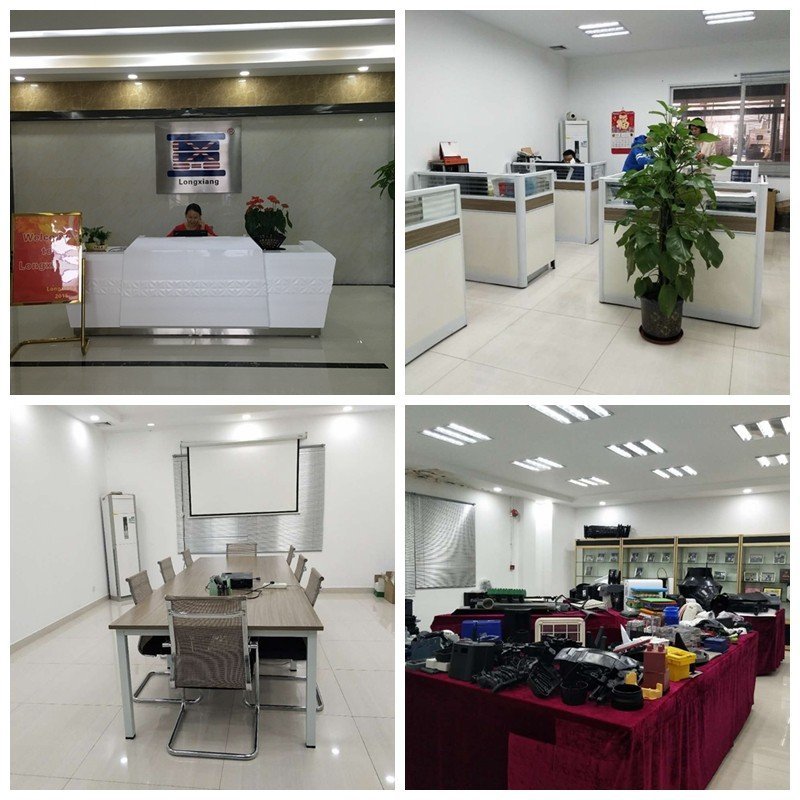
At LXG Mold Tooling, we believe great products start with great tools. As a global leader in injection mold tooling and high-precision plastic manufacturing, we’ve built our reputation on quality, speed, and trust.
Founded in 2000 as part of LongXiang-Ltd, our company has grown into one of China’s most reputable mold-making and injection molding partners. With a 5,000 sq. meter facility, 120+ skilled professionals, and state-of-the-art equipment, we provide end-to-end solutions — from concept validation and rapid tooling injection molding prototypes to mass production with durable injection molding tools.


 20+ Years Experience