If you’re planning to order injection molds and produce plastic parts, one of the first—and most critical—design decisions you’ll make is the wall thickness. Get it wrong, and you risk sink marks, warpage, voids, too-long cycle times, or even un-moldable designs. But done right, you’ll get strong, consistent parts that mold reliably and economically.
Minimum Wall Thickness — “How Thin Can You Go?”
When people ask, “What is the min wall thickness for plastic injection molded parts?”, the real answer is: it depends on material, featur geometry, flow distance, and mold capability. But we can draw useful guidelines.
Common Guidelines & Industry Practice
Many sources suggest ~0.6 mm as a practical lower bound for simple parts. FOW Mould states: “the minimum wall thickness should not be less than 0.6 mm” to avoid issues like sticking or difficult ejection.
Protolabs gives recommended wall thickness ranges per material: e.g. for ABS, 1.143 mm to 3.556 mm.
Minnesota Rubber & Plastics recommends 0.635 to 0.762 mm (0.025–0.030 in) for small parts, 1.02–1.27 mm for larger ones.
Xcentric Mold notes that a 10% increase in wall thickness gives ~33% increase in stiffness. That means thickness matters for performance too.
Some real-world designers push thinner than 0.6 mm, but that often means accepting trade-offs or requiring optimized mold design. Boyan Manufacturing Solutions
So, for most typical thermoplastics like ABS, PP, PC, Nylon, you’ll see min wall thickness guidelines in the 0.6 mm to 1.5 mm range, depending on geometry.
Why You Can’t Make Every Wall Ultra-Thin
Going too thin causes several problems:
Poor flow & incomplete fill: Thin sections offer high resistance to molten plastic flow. If the melt can’t reach the far ends before cooling, you’ll get short shots or weak fills.
Warping & stress: Thin and thick areas adjacent to each other cool at different rates, inducing differential shrinkage and stress. You’ll see warp or twisting. Fictiv advises that wall thickness should not vary abruptly and that walls be ≥ 40–60 % of adjacent walls.
Weakness under load: Extremely thin walls may not handle mechanical loads, impact, or assembly stresses.
Ejection issues: Thin walls might stick or deform during ejection from the mold, especially without sufficient draft or tool support.
From a mold-builder’s perspective, when you send us a design with walls thinner than ~0.6 mm, we immediately look for trouble: is the material suited, is the flow path short, are there ribs needed, what’s the gate location, etc. Sometimes we’ll push the limit, but only if the design can support it.
So when you ask a molder like LXG Mold Tooling for prototype or production tooling, aim for a safe minimum wall thickness that balances performance and manufacturability. Use the guidelines above and verify with mold flow simulation.
2. Maximum Wall Thickness — “How Thick Can It Be Before Everything Breaks?”
Just as there is a lower bound, there’s also a practical upper bound for max wall thickness of plastic injection molded parts. Too thick, and defects creep in. But some designs genuinely require thick sections—for structural strength, heat sinks, or mechanical connection areas.
Typical Ranges & What Defects Appear
Many sources recommend that primary wall thicknesses stay within 3 mm to 5 mm to avoid difficulties. MoldAll states: “the maximum wall thickness … typically ranging from 3 mm to 25 mm, though guidelines recommend staying below 5 mm to avoid defects.”
Some heavy-duty or fiber-reinforced plastics may go thicker: e.g. long-fiber reinforced plastics might have workable wall thickness up to 25.4 mm in niche cases. Protolabs+2Moldall+2
But even in those cases, defect risks rise: sink marks, voids, excessive shrinkage, internal stresses, flash, and very long cooling times.
BoyanMFG mentions that a single-wall thickness of 8 mm is already pushing the limits—sink marks become obvious and cycle time balloons.
Also, the PlasticMoldFactory suggests that localized thick designs should be limited to 6–8 mm, and going beyond that requires special process design.
So while you may see a theoretical “max wall thickness” of 20+ mm in extreme cases, for normal production molds, staying under ~5 mm is common practice.
Challenges in Thick Parts Injection Molding
When you design thick parts injection mold, you face several additional constraints:
Cooling time explosion: Thick sections cool slowly, so cycle times skyrocket. That eats productivity.
Sink marks / caving: As thick insides shrink during cooling, the outer surface may depress inward.
Void formation: Trapped air or gas inside thick cavities may lead to voids.
Warping / internal stress: The core cools slower, outer layers shrink more quickly, creating residual stresses that warp the part.
Material constraints: Some resins don’t tolerate thick sections—they degrade, or don’t flow well.
Tooling complexity: Thick parts often require cores, inserts, or even gas-assist or multi-shot techniques to manage fill and shrinkage.
As a mold-builder, when clients request thick walls, we often propose modified designs: hollow cores, gas assist, insert molding, or overmolding strategies to achieve strength without pure thickness. For example, BoyanMFG shows how overmolding can allow “wall thicknesses over 15 mm” by first molding a core substrate and then overmolding.
Also, designers sometimes assume “thicker is stronger,” but above a point, you get diminishing returns—but drastically increased defects.
So yes, thick parts injection mold is feasible—but it requires careful engineering, special tooling, and often compromise in cycle time or yield.
3. Balancing Thin & Thick: Wall Thickness in Realistic Designs
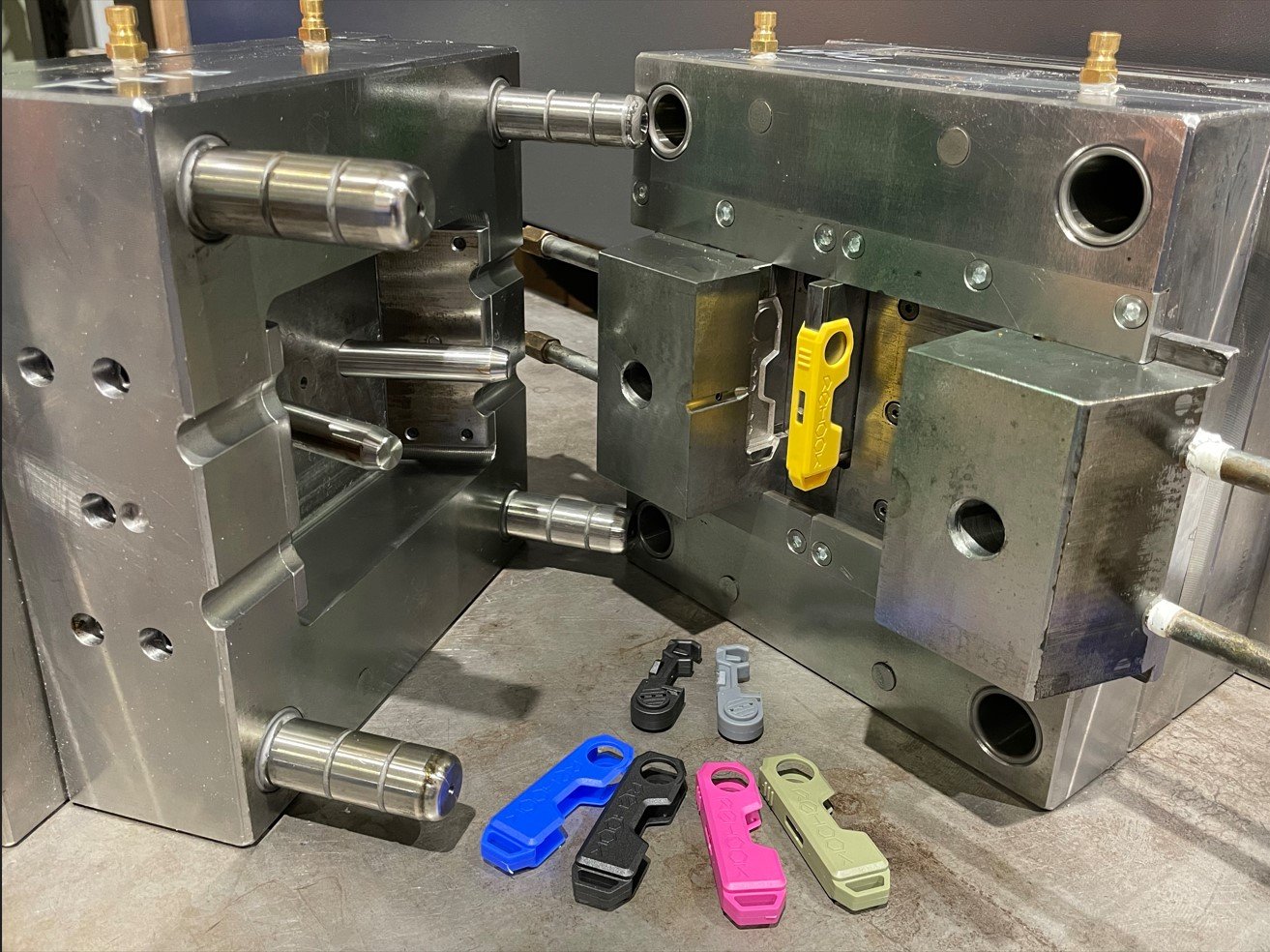
Designing a part isn’t just picking a min or max wall. You need to balance, taper, transition, and use reinforcement features. Here’s how to do it smartly.
Nominal / Uniform Wall Thickness
The ideal is a nominal wall thickness—i.e. most of your part walls should be the same thickness. This encourages uniform cooling and reduces differential shrinkage. Xcentric Mold notes that deviations beyond 10 % in a wall thickness can lead to defects.
Protolabs and others strongly recommend keeping wall thickness uniform .
If you need to deviate (e.g. for ribs, bosses, mounting features), use gradual transitions. Avoid abrupt changes—those are stress concentration zones.
Ribs and Stiffeners
Use ribs rather than thick walls to add strength. Ribs let you get stiffness without adding thick bulk.
Typical guidelines: rib thickness ~50–70 % of nominal wall thickness. Rib height ≤ 2.5–3× nominal wall thickness.
Also ensure adequate draft on ribs (e.g., 0.5°–1°) so they release clean
Gates, Flow Length, and Wall-to-Length Ratios
The flow length-to-thickness ratio is a crucial metric. It defines how far molten plastic can travel given a wall thickness. If the wall is too thin relative to how far it must flow, filling fails.
Fictiv lists flow length ratio for materials: e.g. PP 200–300, ABS 30–50.
That means for very thin walls, the part must be compact or have multiple gates to reduce flow distance.
Cores, Holes & Metal Inserts
For very thick sections, it’s better to core-out than leave solid plastic. Cavities filled with plastic are more prone to sink and voids.
If a thick region is unavoidable (e.g. at a mounting boss), consider insert molding or structural inserts.
Also, internal holes or blind features should not be deeper than about half the hole diameter to avoid internal stresse
4. Guidelines & Examples for Common Materials
To make this more practical, here are sample ranges by material, and notes on extremes. These ranges come from design guides, but always validate with mold flow and your molder.
| Material | Recommended Wall Thickness | Notes on Max / Min Behavior |
|---|---|---|
| ABS | ~1.14–3.56 mm (0.045–0.140 in) | Going beyond ~3.5 mm may cause sink. Some design forums mention ABS above 3.5 mm is hard to maintain sink-free surfaces. |
| Polypropylene (PP) | ~0.64–3.81 mm | PP flows well, so it tolerates thinner designs. Maximum thick sections often limited to ~6–8 mm before defects. |
| Polycarbonate (PC) | ~1.02–3.81 mm | PC is more forgiving in thicker parts but still faces stress and shrinkage when overdone |
| Nylon / PA | ~0.76–2.92 mm | Nylons require careful control due to moisture and internal stresses. |
| Long-Fiber Reinforced Plastics | ~1.9–25.4 mm (0.075–1.000 in) | These can go thick, but still require controlled designs and careful cooling. |
| Others (PE, Acetal, Acrylic, etc.) | Varies | Use standard tables: protolabs, design guidelines, etc. |
These ranges offer good starting points when you send your design to LXG Mold Tooling for review. But always run mold flow and consider gate locations, cooling, and context.
5. Practical Strategies for Orderers (You) to Get Better Molds at LXG
Since you’re ordering molds and parts, here’s how to use this knowledge to get better outcomes from LXG Mold Tooling or any high-quality molder:
a) Early DFM Review & Simulation
Before tooling, ask for DFM (Design-for-Manufacturing) feedback. At LXG we’d simulate your design with flow, warp, and shrink models. That might reveal that a 0.8 mm thick section needs to be bumped to 1.0 mm, or that a boss area needs taper.
b) Specify Uniform Thickness or Gradual Transitions
When you send your CAD, aim for mostly uniform walls. If variation is necessary, make transitions gradual—avoid sudden jumps from 1 mm to 5 mm. This reduces risk.
c) Use Reinforcements, Not Bulk
Rather than making a wall 4 mm thick, you might achieve required stiffness with a 1.5 mm wall plus ribs or gussets. That’s more efficient, molds better, and lowers defects.
d) Cap Thick Sections
If a region requires more material (for mounting bosses, high loads), consider capping it with a thin cover rather than making the entire wall thick. This keeps cross-sections more uniform.
e) Consider Advanced Techniques
For very thick needs, you can leverage techniques like:
Gas-assist injection molding
Insert molding / core-outs
Overmolding / multi-shot
Structural foam molding
These allow you to build strength without the full penalty of thick solid sections.
f) Communicate Key Dimensions Early
When submitting an RFQ to LXG Mold Tooling, highlight critical load-bearing walls, boss areas, or regions where thickness can’t deviate. That helps the mold designer prioritize.
g) Prototype with Intent
Use rapid tooling for prototypes that mimic production conditions. That helps validate thickness, cooling, warpage, etc., before full tool investment.
6. Real-life Examples & Trade-Offs
To make this concrete, here are a couple of common scenarios we see in mold quoting and how we deal with them:
Scenario A: Thin-walled consumer housing (e.g. electronics cover)
You propose a 1 mm wall thickness over 150 mm span. That’s tough but doable in PP or ABS. We’d simulate whether the melt can reach the far end without premature cooling. If not, we might ask for a thicker wall (1.2 mm) or alternate gate placements.
Scenario B: Structural bracket with thick mounting boss
You want a 5 mm wall throughout. But you only need strength near the fastener boss. In that case, we’d propose a hollow section with solid boss, or reinforcement rib rather than full thickness. This reduces shrink and sink risk.
Scenario C: Thick-walled part for industrial housing
You ask for 8 mm everywhere. That’s pushing standard injection molding. We might suggest overmolding or structural foam molding. Or core out large sections so you keep only necessary thick zones.
The point is: designs that deviate from “typical” need extra care and engineering collaboration. At LXG Mold Tooling, we’re used to that. Smart early-stage design often saves rework and rejects in production.
7. Summary & Recommendations
Here’s the distilled advice for anyone ordering molds and designing parts with these keywords in mind:
Min wall thickness often lies between ~0.6 mm to 1.5 mm depending on geometry and material.
Max wall thickness for normal molding is often best kept under ~5 mm, though special materials and techniques can push that higher.
For thick parts injection mold, expect longer cooling times, risk of sink, voids, and the need for advanced tooling or techniques.
Aim for uniform wall thickness across the part. Use ribs, gussets, cores, or overmolding rather than bulk thickness increases.
Always run simulation (mold flow, shrink, warp) and get DFM feedback (especially from your molder).
In your RFQ to LXG Mold Tooling, highlight thickness-critical areas, maximum variations, and part functional requirements so we can properly engineer the mold.
If you follow these guidelines, your molds will perform better, your parts will come out more reliably, and your production costs will be lower.
3 Steps For Precision Manufacturing
Share Your Files
We’ll sign an MNDA and assess manufacturability for free.

Recieve A Quote
Clear pricing and lead times, no
surprises.
Place Your Order
Lock in production and move forward with confidence.
Get A Quote Now and let’s build smarter, faster, and stronger — together.

Our Testimonials
our client say's
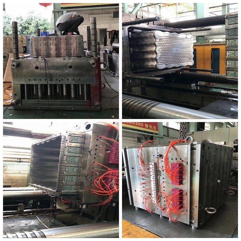
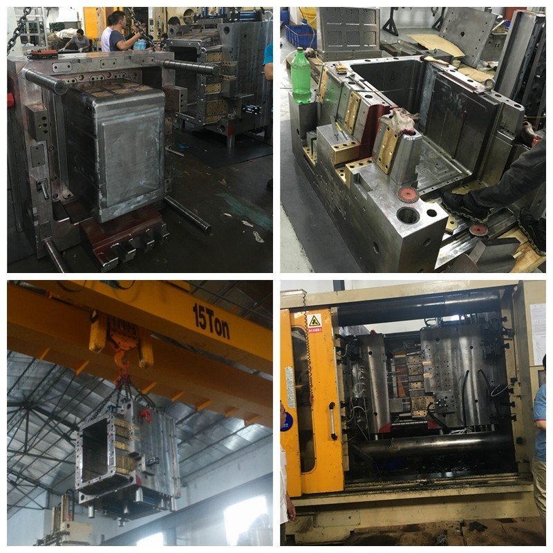
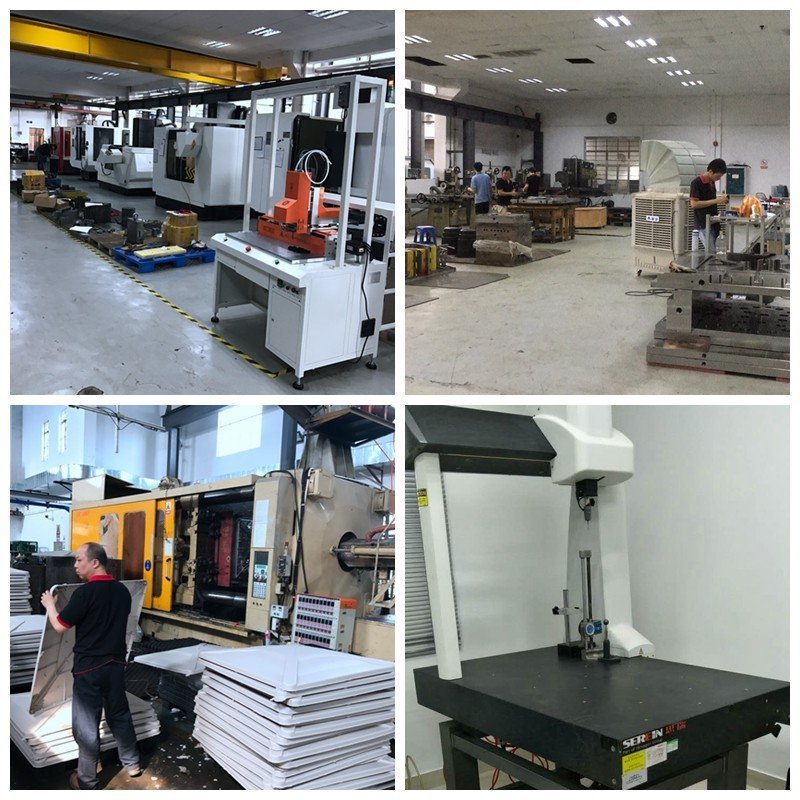
At LXG Mold Tooling, we believe great products start with great tools. As a global leader in injection mold tooling and high-precision plastic manufacturing, we’ve built our reputation on quality, speed, and trust.
Founded in 2000 as part of LongXiang-Ltd, our company has grown into one of China’s most reputable mold-making and injection molding partners. With a 5,000 sq. meter facility, 120+ skilled professionals, and state-of-the-art equipment, we provide end-to-end solutions — from concept validation and rapid tooling injection molding prototypes to mass production with durable injection molding tools.


 20+ Years Experience